Disclaimer
We may earn a commission when you use one of our coupons/links to make a purchase at no extra cost to you. Please support the site by using the links.
One of the first things normally gets done to modify an engine is to fit a performance cam. One of the things that go together with that is a Vernier gear or pulley. With the vernier pulley on the cam, the cam can be set up to whatever the driver wants. You can advance the cam and you will gain power at the top end loose low down torque. If you go the other way and you retard the cam you gain bottom-end torque and loose top-end power. This has always been that case with racing engines. The cam(s) has to be set up to what the driver of the car needs.

Variable Valve Timing (VVT)
Over the years the car manufacturers were looking at making the engines more efficient. Fitting vernier gears on cars as a production part just doesn’t make sense. The question was if they do what do they set the cam too. Power or Torque.
The best would be if they could have an actuator of some sort on the cam that will allow the ECU to swing the cam form max torque to max power. Initially, the VVT systems were on\off systems like the ones that Honda used on there Vtec engines. This gave them the ability to gave torque at the bottom while making power at the high revs they run.
There are a few ways that the manufactures achieved fitting VVT on their engines. One of them was to fit an actuator on the cam itself.

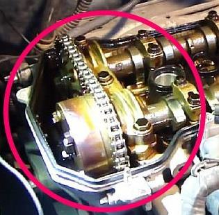
Volkswagen used a different solution on there 20 valve engines. They had a cam bet pulley sitting on the exhaust cam. The crank would turn the exhaust cam. The intake and exhaust cam was linked with a chain. Between the two chain sprocket, they had a chain tensioner. This tensioner was the VVT actuator as well. While maintaining the tension of the chain via oil pressure, it could also move up and down with a solenoid unit. This meant they could tension the one side of the chain more and this would cause the intake cam position to change relative to the exhaust cam.

With most of the on\off VVT systems, you could hear a distinctive change in sound as they revved up. The change in sound was when the VVT shifted over.
Closed-loop VVT
Your normal on\off VVT is open-loop VVT. The ECU switches the cam at whatever RPM it was set to. The manufacturers went a step further. With the emission laws that are getting stricter they needed to find a way to make changes anywhere in the MAPS without the driver noticing the changes. This is were closed loop VVT came in. Every cam on the engine would have a sensor on it. The ECU would monitor the cam position throughout the rev range. It would follow a map on the ECU and try to reach the value. The Actuators are pulse width modulated. This means the cam has a constant 12 colt on them but the frequency varies. By changing the frequency(The time the 12 volt stays on) the cam would move. On the ECU terms, they talk about the duty cycle.
If the duty cycle is 0% the actuator would be completely off. If the duty cycle is 100% the actuator would be on all the time. Some of these actuators can’t run a 100% duty cycle as over time they would overheat and burn out.
What the manufactures also did is increased the range of the VVT actuators. So if the lock position of the cam is the fully advanced position the cam is past its optimum point. The same counts for the fully retarded point. So by using these VVT systems as on\off VVT does not bring the potential of the engine out. You have to run a closed-loop system on these engines. To give you an idea, if the optimum power is at 110 Deg Cam centers on the engine then the rest position could be at 125 Deg, That is 15 Deg past the optimum. Power would have dropped off dramatically.
V & Boxer Engines with VVT
On V & Boxer engines it becomes a bit more difficult. If you want to run an aftermarket ECU you will have to get a decent one. These engines need close control outputs for each cam. You can’t use the same output on the ECU and share it between two cams. Because of where the cam is in the cycle and different friction between the cams the duty cycle will vary. You have that one intake cam needs a 50% duty cycle to move to a certain angle while the other needs 55% or even 60%. So if you drive the two cams of the same signal the cams would stand at different positions. One bank would make nice power and the other bank would be off.
It would also cause that one bank would be running richer or leaner than the other causing you to through even more power out the door. So each cam does needs is own closed-loop system using its own sensor for positioning. The two closed-loop systems can only share the target position map.
Engines with modified aftermarket Cams with VVT
When building race engines that still use the VVT system, stuff can get interesting. Some times you find that when you retard the CAM you will reach the end stop of the actuator and the torque has not started to drop off. This means you could fit an aftermarket actuator that allows you to retard the cam even more. You have to be careful though. As normally the valve to piston clearance is very close. You would have to check that you have deep enough valve pockets on your pistons to achieve the proper angle.
Some people do modify the standard actuators to reach the angles they need to. You are very limited though on what you could reach.

When doing mods like this you need to make certain that there is enough meat for the metal seals to function properly. Also like I mentioned earlier, you must check that the valve to piston clearance allows you to do that.
So what is the difference between VVT and VVL
VVT is Variable Valve timing where VVL is Variable valve lift. This is just a way that the manufacturers get the engines to be super light on petrol and give good emissions results. One again there is many ways to achieve VVL. Volkswagen has a setup that there are two lobes next to one another. The one lope is a low lift lobe and the other is a high lift lobe. They have an actuator that will move the cam from side to side. So on low throttle positions, they would run on the low lift cam that will allow a small amount of air into the cylinder. Doing this you need less fuel.
When acceleration and you are at a higher throttle position the cam would move so that the high lift lobe is in use. Now it allows more air to enter the cylinder which needs more fuel and makes more power. These type of systems is on\off systems as it is either the one lobe or the other.
Over the years running high-performance cams engines got heavy on fuel. with all this new technology you could have the best of both worlds. Light on fuel and a lot of power.
« A really sad time for me | The Outcome of the 917 »
Check out these link buttons!
Parts by Brand Support the website by becoming a Patron Make a donation with GoGetFunding Click here if you would like to Subscribe! Click here to check out some of the other posts Click here to make a contribution to my latest Project car Click here to setup a monthly contribution to website Click here to check out the forum page Click here to check out the Top 100 Auto Blogs
